Software Rendering from Scratch
By Amine Rehioui, Dec 12, 2021
Graphic cards are now ubiquitous. Their main task is accelerating calculations needed by 3D graphical applications. There are many APIs used to interface with them, such as DirectX and OpenGL. But how did programmers do it, before the widespread adoption of graphic cards? The short answer is they developed the calculations necessary for 3D graphics by hand and ran them on the CPU. This is what is meant by Software Rendering and this is what this article is about.
Source Code
Check out Platz on Github, a 3D Software Renderer written in C++ and illustrating the concepts in this article.
Techniques
There are a few techniques for producing 3D graphics on the CPU. Ray-tracing is the most physically accurate, but the most expensive to calculate. It is more appropriate for offline rendering. Rasterization is more approximative but more suitable for real-time rendering.
Ray-tracing
Ray-tracing consists in visualizing the world by simulating the interactions between “light” and “matter”. It is done by sending rays of light from light sources onto the world and calculating their trajectory based on the nature and orientation of surfaces that are crossed by the rays. Then, for each ray that “makes it” to the viewer, color is determined at the corresponding screen location, based on the history of the ray. For more details on this technique, check out Introduction to Raytracing.
Rasterization
Rasterization consists in converting an arbitrary 3D representation into a discrete 2D representation, sometimes called a “raster” image. This is based on two main approximations. First, the world is approximated as a list of geometric primitives, usually triangles. Second, each triangle is projected onto the screen and filled based on an approximation of the conditions at each point in the triangle. We will discuss this approach.

Rasterization
3D representation
Triangles are ideal candidates for representing 3D geometry. Grouping triangles can represent complex shapes, to a varying degree of detail. On the other hand, their structure is so basic that splitting a triangle can only yield 2 triangles. We will represent the world as a list of triangles.
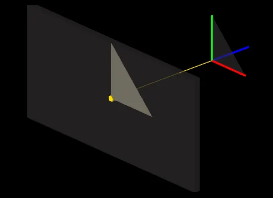
Conversion to 2D Screen Space
In order to draw 3D triangles on a 2D screen, we must first set a convention, that defines how the origin of the 3D space and the origin of the 2D space are related to each other. This is arbitrary. So we will use a fairly common convention: The origin of the screen is at the top left corner, with the X and Y axes pointing Right and Down respectively. For the 3D origin, the X, Y, and Z axes will point Right, Up, and Forward. This is known as a Left Handed Coordinate System and is illustrated below:
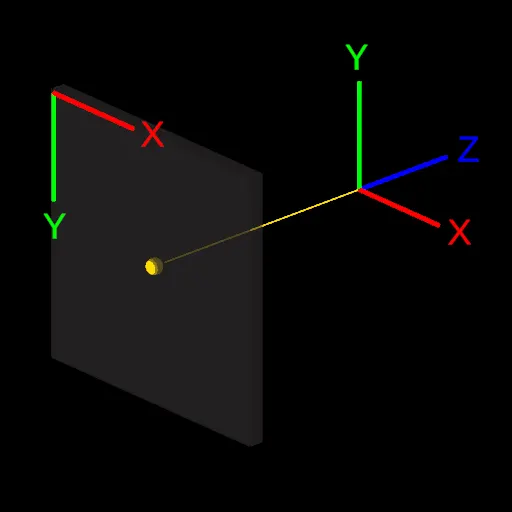
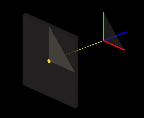
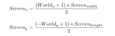
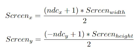
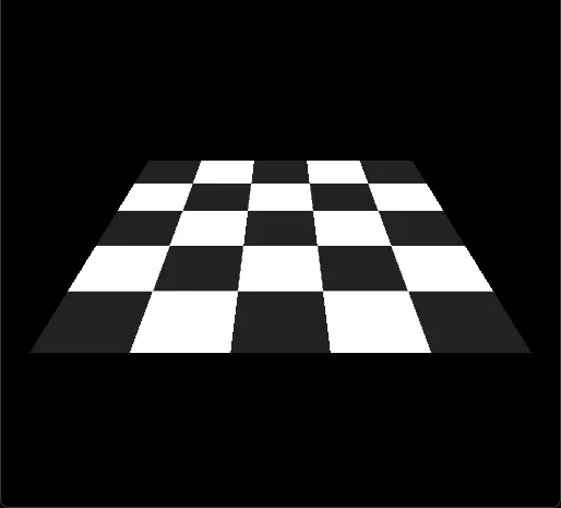
This convention means that a 3D point at the origin (0, 0, 0) will end up in the center of the screen. But where should a point be located to end up on one of the edges of the screen? As a convention, we can consider 3D coordinates ranging from -1 to 1 to span the whole screen. This makes it simpler later to discard elements that are outside of the screen. Given this convention, a triangle at the origin would appear like in the following illustration, assuming the screen has a square resolution:
If the screen is rectangular, the triangle will look distorted in the horizontal X dimension:
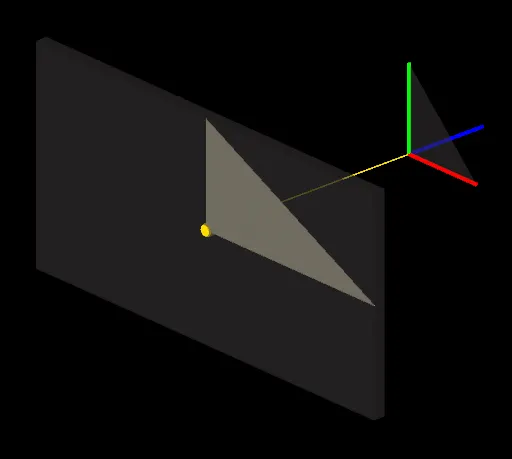
To fix it, we must take the screen aspect ratio into account. This is done simply by dividing the X coordinate by the screen’s aspect ratio:

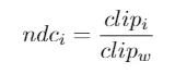
This is the core idea behind converting triangles to screen space. Since we ignored the Z coordinate so far, this can be referred to as Orthographic Projection. There are different kinds of projections, and to support them in a generic way, we can use linear algebra: This consists in transforming the vertices using a projection matrix, before converting them to screen space. Here is a reference of the whole process, starting with a Perspective Projection matrix:
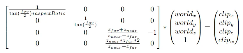
- fov: The field of view in Radians
- aspectRatio: The screen width over the screen height
- zNear: The distance from the viewer where clipz / clipw= -1
- zFar: The distance from the viewer where clipz / clipw = 1
Filling Triangles
Once the triangle is on screen, we need to figure out which pixels are part of it, and then determine their respective colors. A useful way to do it is to use Barycentric Coordinates. They are related to how a point is positioned relative to the triangle corners. If a point is inside a triangle, its barycentric coordinates are all positive and add up to 1. Otherwise, the point is outside the triangle.
A naïve implementation would be to check the barycentric coordinates of all pixels on screen. A common optimization is to first calculate a bounding rectangle around the triangle, then only traverse pixels within it:

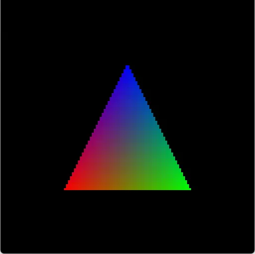
Coloring
The simplest way of coloring a triangle is to use one color everywhere. This is fine but not very exciting… A more sophisticated way is to use 3 colors: one for each vertex. Then, we color the triangle based on a mix of the 3 colors. And very fittingly, we can recycle the barycentric coordinates that we used in the “pixel inside triangle” test. They are perfect as factors in the color mix.
Texturing
In order to apply a texture to a triangle, we should first define which part of the texture to apply. Then, for each screen pixel, we determine a corresponding pixel on the texture and borrow its color. In computer graphics terminology, texture pixels are referred to as Texels.
Defining the part of the texture to use is done by assigning texture coordinates to each vertex. The idea is simple, texture coordinate range from [0, 0] to [1, 1], which corresponds by convention to the top left texel and the bottom right texel, respectively. Like we did for coloring, we determine an interpolated texture coordinate for each pixel, based on its barycentric coordinates, and use it to look up the corresponding texel.
Perspective correct interpolation
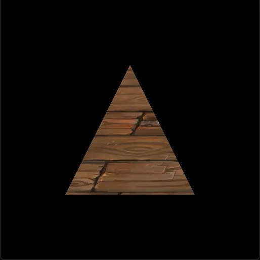
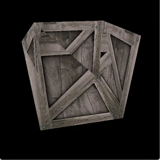
There is a slight problem with the approach above - When the geometry is at an angle with respect to the view, we notice a strange warping in the texture mapping:

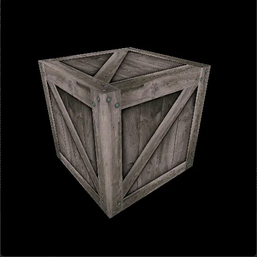
This is a classic mistake in software rendering: Interpolating 3D vertex information using barycentric coordinates of a 2D triangle doesn’t take perspective projection into account. Since we project a 3D triangle onto a 2D screen, we should take into account the Z coordinates of the vertices when interpolating vertex information, because farther features are supposed to look smaller. This correction is called Perspective Correct Interpolation.
World Transform
Rendering one triangle successfully is a good start, but in practice, it’s useful to render entire objects, which are made of many triangles. In addition, it’s useful to move objects around, rotate, and scale them. Although it’s possible to move an object by changing the vertex positions on all its triangles, it’s much better to manage the position, rotation, and scale information at the object level, and use linear algebra to transform the vertices at each object.
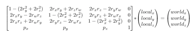
Transforming vertices needs to happen before projecting them. The same projection can be used for all objects, but each object can have its unique transform. We can represent the position p and the rotation r (in Quaternion form) of an object in a World Matrix, and use it to transform the vertices of the object. It would look like this:
Camera
So far, we have been using a perspective projection matrix to project 3D triangles onto the screen. We have always been looking at them from the same viewpoint. What if we want to look at them from a different viewpoint? Again, we can use linear algebra.
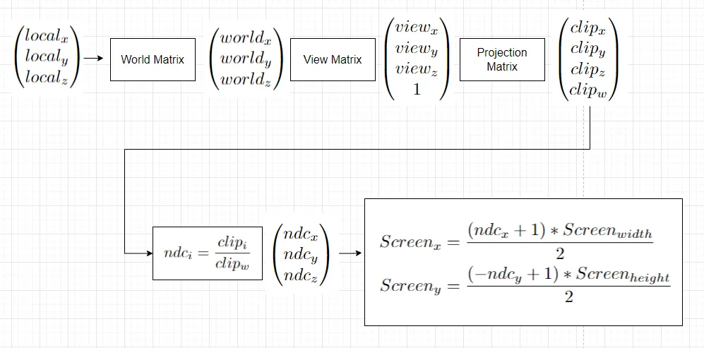
To simulate a camera, we can imagine a virtual object that has a position and an orientation corresponding to the camera viewpoint we want. We construct a world transform based on that, and then invert it, to obtain a View Transform. Finally, we apply this view transform to the world space vertices prior to projecting them. This completes the entire 3D transformation pipeline, from local space to screen space, which looks like this:
Zbuffer
If we render triangles that are overlapping from the camera point of view, we may notice the following problem:
Some pixels that should be in the back are drawn on top of pixels that are in front. This is because the triangles are arbitrarily traversed for rendering, so nothing guarantees that surfaces closer to the camera will always be drawn in front. To fix this problem, we need to keep track of the distance of each pixel with respect to the camera. This consists of the Z component of the NDC position that is obtained after projection, and is referred to as depth. We ensure that pixels with a higher depth, i.e. farther from the camera are discarded if a pixel with a lower depth was already drawn at the same location.
This technique is referred to as Z-buffering. We initialize a screen-sized buffer with the maximum possible depth value, at the beginning of every rendering loop. Then, each time a pixel is processed, we check if its depth is smaller than the recorded depth. If it’s not, we discard it. Otherwise, we update the recorded depth with the pixel’s depth, and we draw it.
Clipping
Clipping means discarding non-visible elements. In software rendering, clipping is an important optimization, that ensures pixels on non-visible parts are not processed. Modern graphic cards perform this in a clip coordinates, which are obtained after projecting the vertices. We will implement it in world-space instead, as it’s more generic and more reusable in other contexts.
First, we need to understand the concept of a Frustum: It’s the volume that is visible by the camera. It can be represented as a set of 6 planes:
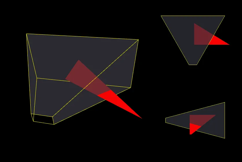
Second, we need to ensure that geometry that is outside or that intersects the frustum is clipped. All the triangles are tested against it. Those that fall completely outside are discarded, those entirely inside are kept, and those that intersect are clipped. Here is how to determine the 6 frustum planes:
And here is how to test a triangle against a plane, and slice it accordingly if they intersect: Triangle/Plane clipping.
Back-face culling
When rendering opaque triangles naively, it’s common to waste processing time on triangles that are completely obstructed, for example the triangles on the inside of an opaque cube:

To avoid this, each triangle can be considered as having 2 sides: a front-facing and a back-facing one. A convention is to render front-facing sides and discard back-facing ones. There are exceptions, especially for rendering transparent objects, because their back faces are partially visible through their front faces.
For opaque triangles, we determine which of its sides is currently facing the camera. If it’s the back one, we reject it early in the rendering process. This step is easy to do using the NDC coordinates of the triangle, because their local Z axis is exactly parallel to the view direction.
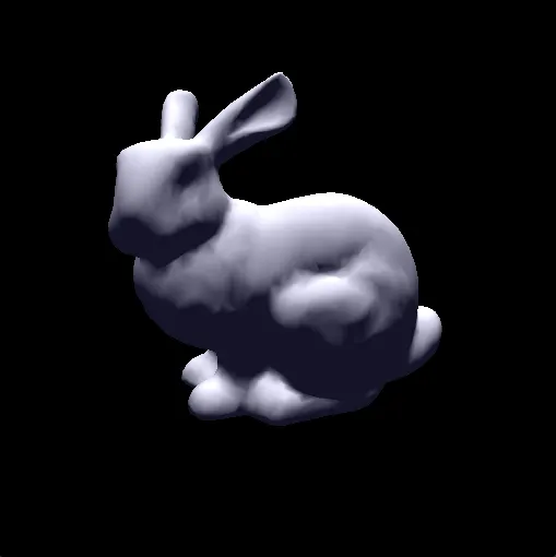
Model Loading
Before implementing more interesting features such as shading and shadowing, it’s nice to use more interesting geometry than triangles and cubes. We will pick the very simple OBJ format and write a loader for it:
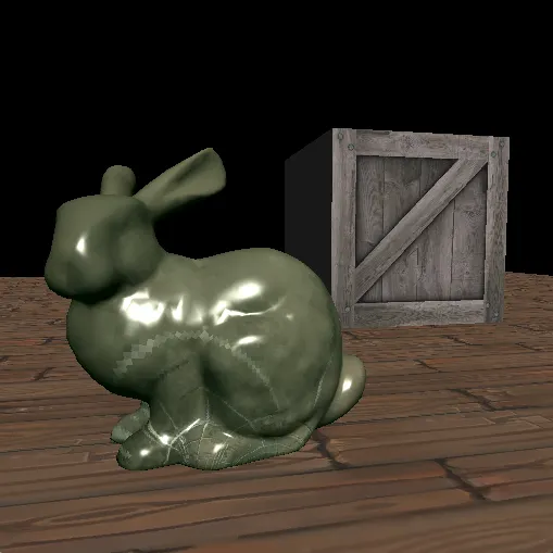
Lighting
It’s time to introduce lighting! The core principle is that light originates from light sources, bounces around the world, and ends up in a viewer’s pupil. By “bouncing around”, I mean that each time light interacts with a surface, it is absorbed by an amount, and reflected in a direction, based on the properties of the surface. At a more fundamental level, light comes out with initial energy and direction, and basically loses energy and changes direction upon each contact. Ultimately, the colors we see are a representation of the remaining energy, and their intensity is modulated by the final direction.
This deserves a separate article, as computer graphics have come a long way and there are many modern techniques that deal with this realistically. For now, we will keep things simple and implement a classic method that is based on many approximations: The Phong Shading Model.
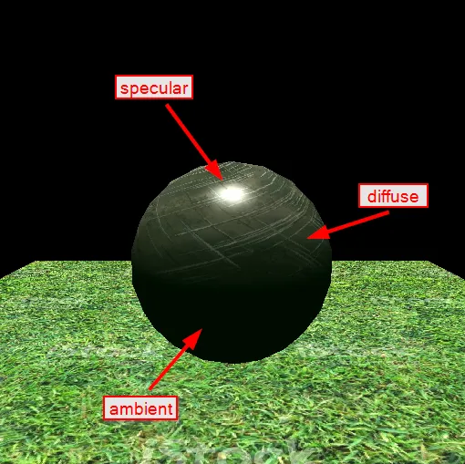
There are 3 main contributors to the result when using Phong shading. First, there is an Ambient Color. It represents the color on surfaces that are completely in the dark. A good practice is to set it to a very dark tone of the most preeminent color in the surroundings. For example, in an indoor environment where the walls are blue, the ambient could be a very dark tone of blue. If we are outside in a green forest, the ambient could be a very dark tone of green. The idea is that surfaces are never really completely in the dark, there is always some indirect lighting that is reflected off of the environment.
The second main contributor is the Albedo Color. It represents the inherent color of surfaces. But unlike the Ambient color, it’s combined with the amount of direct lighting that is reflected off the surface, giving a final Diffuse Color. In order to determine how much light is reflected, we consider the concept of a Surface Normal. It’s a representation of how a surface is oriented in space. The light amount reflected by the surface depends on the direction of the incoming light relative to the surface normal. It’s at a maximum if they are parallel, and is zero if they are perpendicular.
The last contributor is called Specular Highlighting. This adds a bit of realism by approximating the small highlights on shiny surfaces. It depends on the shininess of the surface, its normal, and also the viewing angle.
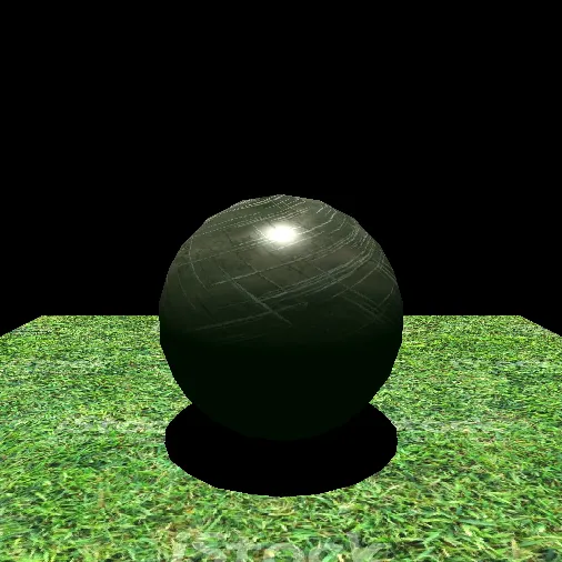
Shadowing
To handle shadows, we will simply darken the result of the previous lighting step, by a factor that depends on the amount of light that is received on the corresponding pixel by the surface. To determine the amount of light received at a particular pixel, we simply trace a ray towards all light sources. If a light source cannot be reached because the ray collided with a surface before reaching it, we subtract its influence and continue checking the other light sources.
Source Code
Check out Platz on Github, a 3D Software Renderer written in C++ and illustrating the concepts in this article.